Setup
To get the Mobile Measurement System up and running you need to install its software and to connect the measurement equipment. First you need to get the software up an running.
Software installation
System architectures
linux/386
linux/amd64
linux/arm/v6
linux/arm/v7
linux/arm64
Installation
Prepare your system
sudo apt-get update
sudo apt-get upgrade
sudo apt-get install docker docker-compose git -qq -y
sudo addgroup docker
sudo usermod -aG docker $USER
sudo service docker start
sudo systemctl enable docker
Note
On some systems docker might not be available in the standard distribution repositories. Check the internet for guidance!
Copy the code base
git clone https://gitlab.dlr.de/as-boa/mobile-measurement-system.git
If you are planing to use I²C oder SPI sensors (standard use case) you need to register FTDI udev-rules
cd mobile-measurement-system/setup
bash ./install_usb.sh
Download and start the container stack:
cd ..
sudo docker-compose up -d
As a sanity check make sure four containers with an identifier MMS_* are up and running (no restarting)
sudo docker ps
This should look similar to:
[...]   IMAGE                              [...]   STATUS         PORTS                                       NAMES
[...]   nginx:1.17                         [...]   Up 1 second    0.0.0.0:80->80/tcp, :::80->80/tcp           MMS_NGINX
[...]   niehaus/mms:latest                 [...]   Up 1 second                                                MMS_SENSOR
[...]   niehaus/mms:latest                 [...]   Up 2 seconds   0.0.0.0:8000->8000/tcp, :::8000->8000/tcp   MMS_GUI
[...]   timescale/timescaledb:1.7.4-pg12   [...]   Up 3 seconds   0.0.0.0:5432->5432/tcp, :::5432->5432/tcp   MMS_DB
The MMS is installed now and can be accessed on the hosting machine via the browser using http://localhost or via other devices on the network via http://<host-ip>/.
Please refer to the user manual for operating instructions.
Sensor datasheets can be found in the documentation section of the web interface or the hardware description of this documentation.
Software update
To specify the new software version change the MMS_VERSION variable in your .env file to equal your desired version. Use the latest tag to refer to the most recent stable release associated to the main-Branch. Use the dev tag to get the current devolopment version. An overview of all release tags can be found on Docker Hub Registry. If you want to ensure consistency or to avoid incompatiblity issues due to i.e. api-deprecations make sure not to use latest and pin the version instead.
Online systems
Updating a mobile measurement system with access to the internet to a new release via:
cd <directory of docker-compose.yml>
docker-compose pull
docker-compose up -d
Note
When using shared IP adresses you might be prompted that your docker quota is exceeded.
Workaround: Signup at Docker Hub and after confirming your account run docker login in your terminal and enter your credentials.
You now have a personal quota.
Offline systems
Switch to an online system download the desired docker image. Note that you need docker on that online system to be installed, too. For downloading the image use
docker pull niehaus/mms:<version>
where <version> shall be replaced with your intended version tag.
Consequently, you need to save the image to file
docker save -o mmsOfflineImage.img niehaus/mms:<version>
Now transfer the file to your offline system and load the image
docker load -i mmsOfflineImage.img
Update MMS_VERSION in the .env file on your offline system and run the update
docker-compose up -d
docker-compose restart
Uninstall
Stop all container and remove
docker-compose rm -vfs
Remove unused volumes
docker volume prune
Delete /var/lib/mms via
sudo rm -rf /var/lib/mms
Troubleshooting
Use docker ps to check if all containers are running.
If a container keeps restarting check out the
docker logs <CONTAINER NAME>
For the container responsible for reading data from measurement devices use
docker logs MMS_SENSOR
To navigate inside a running container and to execute commands from within use
docker run -it --net=mms2_default --privileged <CONTAINER NAME> bash
Raspberry Pis
Wifi Client
A wifi access point for Raspberry Pis can be installed on the system level using the installation script in the setup directory setup/install_pi_ap.sh.
Default parameters:
Gateway/Device IP: 192.168.4.1
SSID: YOUR_SSID
Password: YOUR_SECURE_PASSWORD
max. 20 dhcp clients
- To alter these settings modify
hostapd configuration file at
setup/setup_files/hostapd.confname server configuration at
setup/setup_files/dnsmasq.confnetwork translation at
setup/setup_files/nat_config.conf
Also usefull
- After cloning images shrink using:
Hardware
A list of supported devices and where they can be ordered is presented in the following
Sensors
A full list is included in the featured sensor section. The following subset can be ordered directly of the shelf.
Sensor type |
Quantities |
Supplier |
Article Number |
Note |
|---|---|---|---|---|
SHT 85 |
Temperature |
Digi Key |
1649-1110-ND |
|
Humidity |
||||
SFM3000 |
Volume flow |
Mouser |
403-SFM3000-200C |
add socket cap |
SFM3200 |
Volume flow |
Mouser |
403-SFM3200-AW |
add socket cap |
SFM3300 |
Volume flow |
Mouser |
403-SFM3300-AW |
add socket cap |
SFM4100 |
Volume flow |
Mouser |
403-SFM4100AIR |
|
SFM4200 |
Volume flow |
Mouser |
403-SFM4200AIR |
|
SDP810 (125Pa) |
Differential pressure |
Digi Key |
1649-1073-ND |
add socket cap |
Temperature |
||||
SDP810 (500Pa) |
Differential pressure |
Digi Key |
1649-1074-ND |
add socket cap |
Temperature |
||||
BME280 |
Absolute pressure |
Digi Key |
1568-1706-ND |
Qwiic compatible |
Temperature |
||||
Humidity |
||||
MAX31865 |
Temperatue |
Digi Key |
1528-1804-ND |
Add 4-Wire PT100 RTD |
SCD30 |
CO2 concentration |
Digi Key |
1649-1098-ND |
|
Temperature |
||||
Humidity |
||||
SCD41 |
CO2 concentration |
Digi Key |
1649-SEK-SCD41-SENSOR-ND |
|
Temperature |
||||
Humidity |
||||
SMGAir 2 |
Volume flow |
Ingenieurs Büro Peter Stehle |
||
Temperature |
||||
Abs. pressure |
||||
S8000 |
Dewpoint |
Michell Instruments |
||
Temperature |
||||
ADS1015 |
Voltage |
Mouser |
474-DEV-15334 |
|
NAU 7802 |
Bridge Sensor |
Mouser |
474-SEN-15242 |
|
SPS30 |
Particle matter sensor |
Mouser |
403-SPS30 |
Periphery
To connect I2C to the Host devices USB port a FTDI232 is used in combination with an I2C multiplexer to allow for identical sensor types on the same I2C bus. Bill of materials (1 mux box):
Part |
Supplier |
ID |
Note |
|---|---|---|---|
FT232H |
Digi Key |
1528-1449-ND |
Any breakout board will work |
BOB-16784 |
Digi Key |
1568-BOB-16784-ND |
All TCA9548A boards will work |
Qwiic Cable to Wire |
Digi Key |
1568-PRT-17260-ND |
Cut in half and solder to FTDI232 Breakout board |
Note
In the future a PCB with FTDI and TCA9548A would make manual soldering obsolete and would reduce its dimensions.
Cables
In general it is adviced to keep cable connections as short as possible to reduce the risk of electromagnetic interferences (EMI). Further it is adviced to favor longer USB cables over long I2C cables. Cables that were used successfully:
Part |
Supplier |
ID |
|---|---|---|
Qwiic - Qwiic 500mm |
Digi key |
1568-1713-ND |
Qwiic - Qwiic 100mm |
Digi key |
1528-4210-ND |
SHT85 - Qwiic |
ESTO |
custom made |
SFM/SDP - Qwiic |
ESTO |
custom made |
Raspberry Pi
Base parts |
Note |
Supplier |
Order ID |
|---|---|---|---|
Raspberry Pi 4 |
min. 4GB |
Digi Key |
1690-RASPBERRYPI4B/4GB-ND |
5V power supply |
Digi Key |
1690-RPIUSB-CPOWERSUPPLYBLACKEU-ND |
|
Case (Din-Rail) |
Digi Key |
1778-DINH03-ND |
|
Real Time Clock |
Digi Key |
1597-1391-ND |
|
LED-Button |
red |
Conrad |
4016139335087 |
LED-Button |
green |
Conrad |
4016139335148 |
Set FTDI Identifiers
If you are planing to use FT232 USB to I2C/SPI converters you need to assign unique device identifiers. This is well documented in the pyFTDI project. An example script can be found in the pyserialsensor subproject which is responsible for the sensor communication.
Minimum working examples
In the following the minimal working example for different interfaces is described
UART
- Material:
- Steps:
Connect to the host device by entering its network address in the web browser of a device within the same local network.
Connect the SPS30 to the host device. The number of COM-ports in the interface footer should increment.
Navigate to the setup menu and click the yellow button in the center to start an initialization process. After completion the sensor should be recognized and a green start button on the top right of the header menu should be visible.
Click on the start button. It should switch to a red stop button and a red Live menu entry should appear in the header menu.
The live menu displays current measurement values. If you want to see a visualization of the measurement values, navigate to the visualization menu.
I2C
- Material:
A host system with at least 1 free USB port
FT232H Breakout board (Mouser , DigiKey , Reichelt , Datasheet)
Environmental sensor BME280 (Humidity, Temperature, Ambient pressure) (Mouser , DigiKey , Reichelt , Datasheet)
If you are using a Qwiic Multiplexer add Qwiic wires to conveniently connect FTDI + MUX and MUX + sensor. (Mouser , DigiKey , Distrelec )
- Wiring:
SDA: Connect D1 and D2 to the blue wire (Data in and Data out)
SCL: Connect D0 to the yellow wire (Clock)
Vin: Connect 5V to the red wire (supply voltage)
GND: Connect GND to the red wire
Connect D0 and D7 (clock stretch)
If you are not using a Sparkfun TCA9548 breakout board connect D0 and 5V with a 4.7kOhm resistor and D1 and 5V with a 4.7kOhm resistor
Pt100 breakout boxes
This projects supports the use of 4-wire Pt100 RTD probes. The measurement of the sensor resistance together with a analog to digital conversion is done on a MAX31865 IC and is evaluated via SPI. There are two different implementations supported by the mobile measurement system.
up to 5 Pt100 using one GPIO per MAX31865 as channel select
up to 16 Pt100 using channel select multiplexing (via CD74HC4067M)
You can either use only 5 channel versions or 16 channel pcb versions of the breakout boxes simultaneously.
5 channel Pt100 box
This can be set up easily on a breadboard for quick testing purposes. For a more reliable version use the 16 channel version.
Bill of Materials
Wiring
D0 pin of the FT232H to each CLK of the MAX31865 breakout board.
D1 pin of the FT232H to each SDI of the MAX31865 breakout board.
D2 pin of the FT232H to each SDO of the MAX31865 breakout board.
For each MAX31865 connect CS to one of the D3 to D7 pin of the FT232H
For each MAX31865 connect F- and RTD- to one side of the 4-wire Pt100 and F+ and RTD+ to the other.
In Settings/General select SPI mode GPIO to indicate you are using the 5 channel version.
16 channel Pt100 box
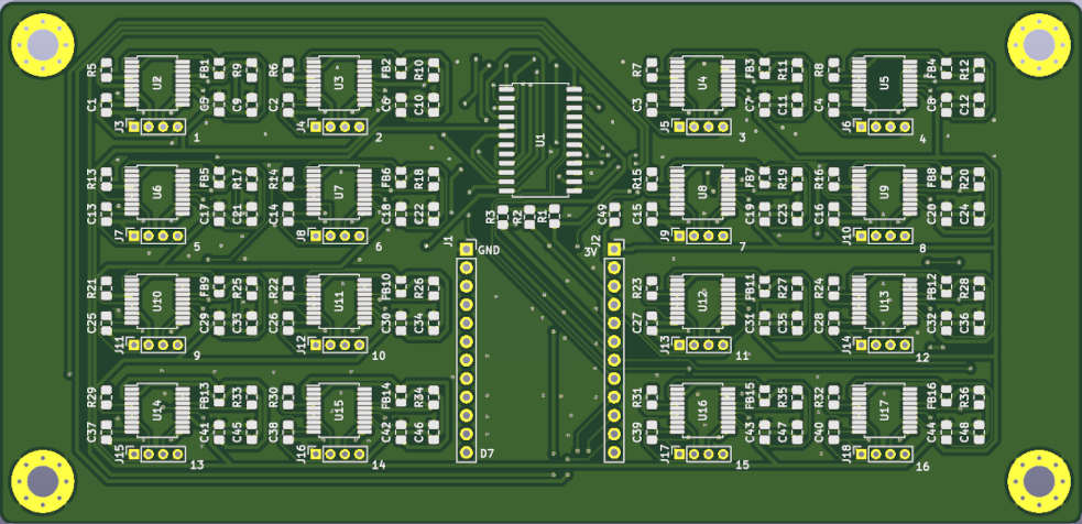
The layout of the PCB, the KiCAD project and the gerber-export can be found here.
Bill of Materials
Multiplexer CD74HC4067M
Pt100 transducer MAX31865xAP
Capacitor CAP CER 0.1UF 50V X7R 0805
FERRITE BEAD 120 OHM 0805 1LN
Reference resistor (for Pt100) ERA-6AEB431V - RES 430 OHM 0.1% 1/8W 0805
Resistor RES 10K OHM 1% 1/4W 0805
Conn_01x12_Female
PIN - Socket B4B-ZR(LF)(SN)
Wiring
Solder a pin row to each side of an upside down Adafruit FT232H breakout board. Plug the FT232H into the socket rows of the PCB. Make sure to connect the correct pins (12 Pins on the socket and 11 pins on the the Adafruit FT232H) and double check if GND matches GND and 3.3V matches 3.3V on the FT232H.
Next you need to connect the 4-wire Pt100 to the board. For each channel connect pins 1+3 to one side of the Pt100 and 2+4 to the other. You can use JST PHR Female 2mm, 4-pin 1 row (RS Components, Farnell, DigiKey) with self or pre-crimped wires.
A layout of a breakout box can be found here. The boxes can be built using the following parts